The frame was crooked.
We had this issue every year. As a driver, this bothered me because it would cause the car to turn more in one direction than the other. As the leader of the frame team, this bothered me because an asymmetric car is a car that is not manufactured to tolerance. This makes my FEA much less reliable. But at the end of the day, this bothered me because I take pride in my work. Also, my teammates put in way too much work for me to be ok with letting their frame be crooked. So, the year I was the frame lead, I was determined that the frame would be perfect. If you want to see the design part of this project, click here
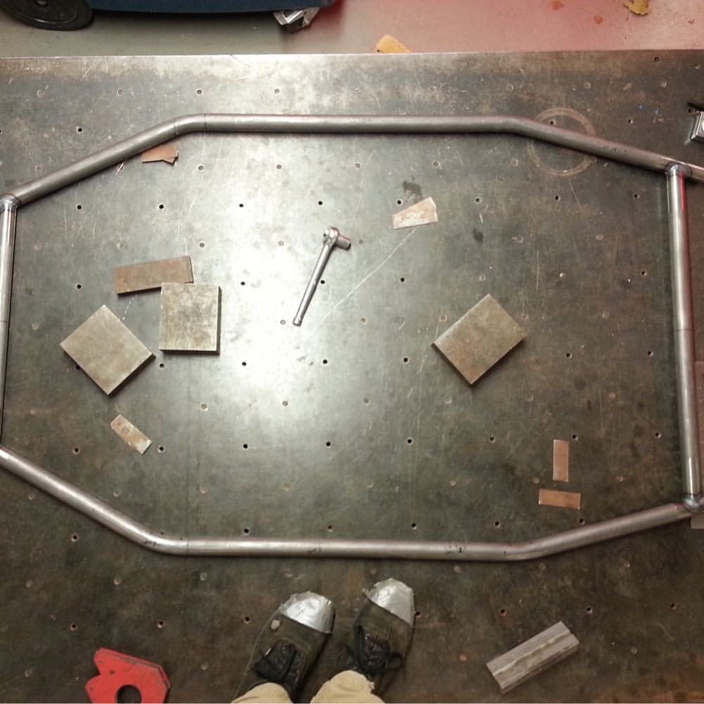
The original method for laying out the firewall.
In previous years, the first thing we did was to manufacture the tubes for the firewall. After they were completed, we would bolt them down to the welding table and weld them. The trouble is, it’s hard to accurately measure tubing, much less make small adjustments while keeping everything else in place. That combined with the warping from welding would usually end up causing our firwall to be accurate to about a half inch of tolerence. The first thing I wanted to fix was our fixturing method. If the tubes weren't in the correct position in the first place, they wouldn't be square, no matter how well I welded them.
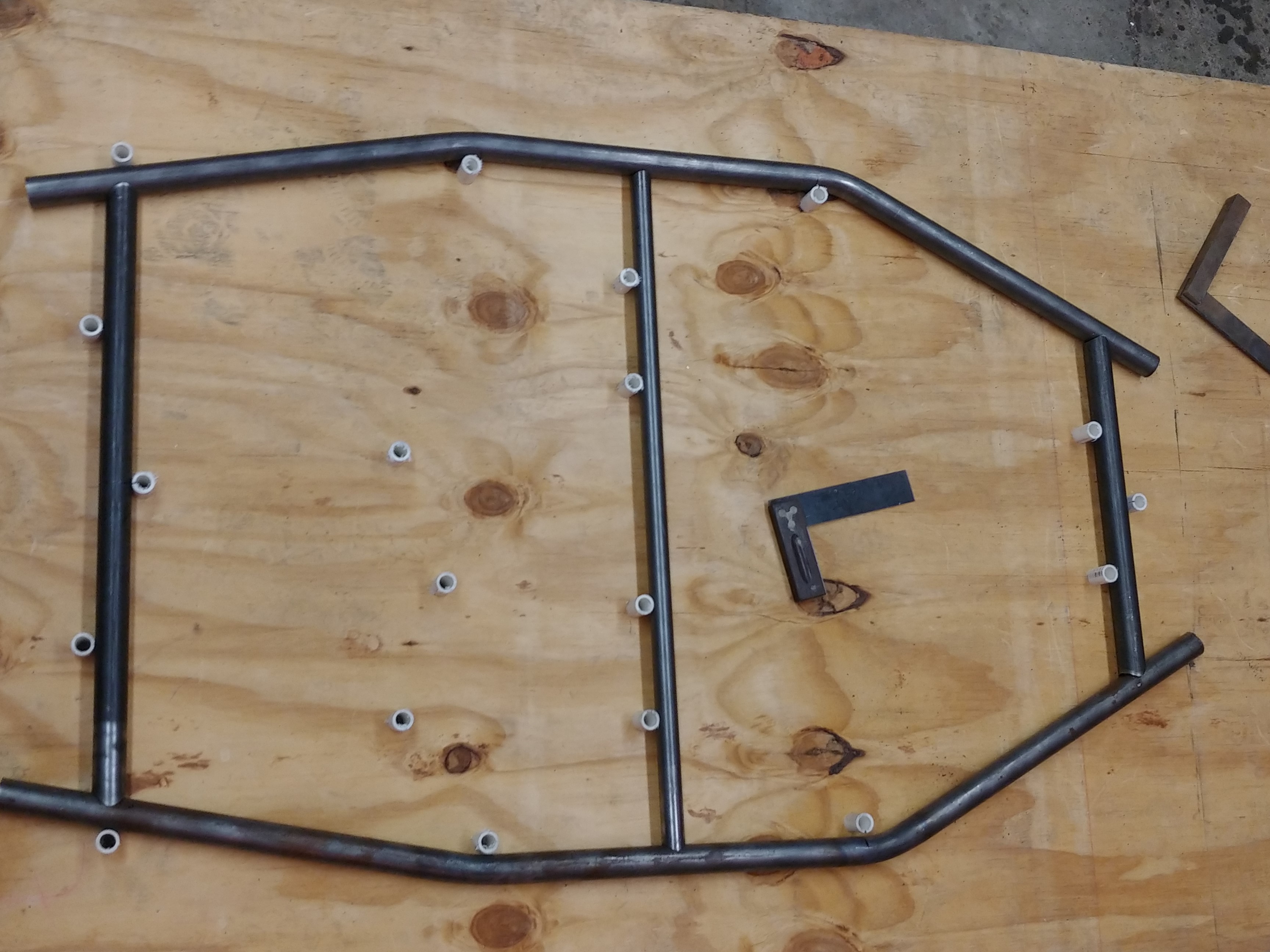
The tubes of the firewall, placed in a fixture I designed.
The solution I settled on was using a CNC router to manufacture our fixture. I took a piece of plywood and used the router to precisely drill holes in it. Then, I cut up some pvc pipes to act like pegs and put them into the holes with about 2 inches sticking out to support the firewall. This not only let me position the components of the firewall with high accuracy, it also held them in place for welding. I had talked to some professional welders at 'Ark and Flame' to get their advice on welding the firewall. With their advice, I was able to seam the firewall with minimal warping.
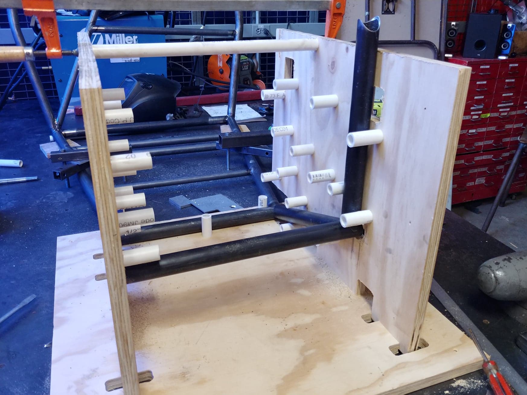
Laying out the tubes in the footbox.
This method took our tolerance down from a half inch to a sixteenth, so of course we also wanted to use it for the footbox. For this, I needed to have the plywood support a 3-dimensional structure. All it took was a quick chat with the team’s advisor, some clever cuts, and boom: we had a square footbox.
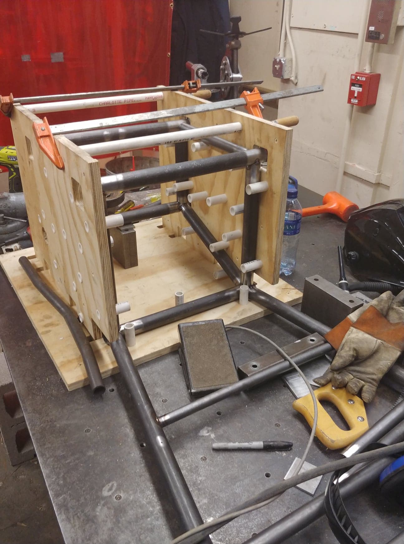
All of the tubes are in place and tacked, ready to be seamed.
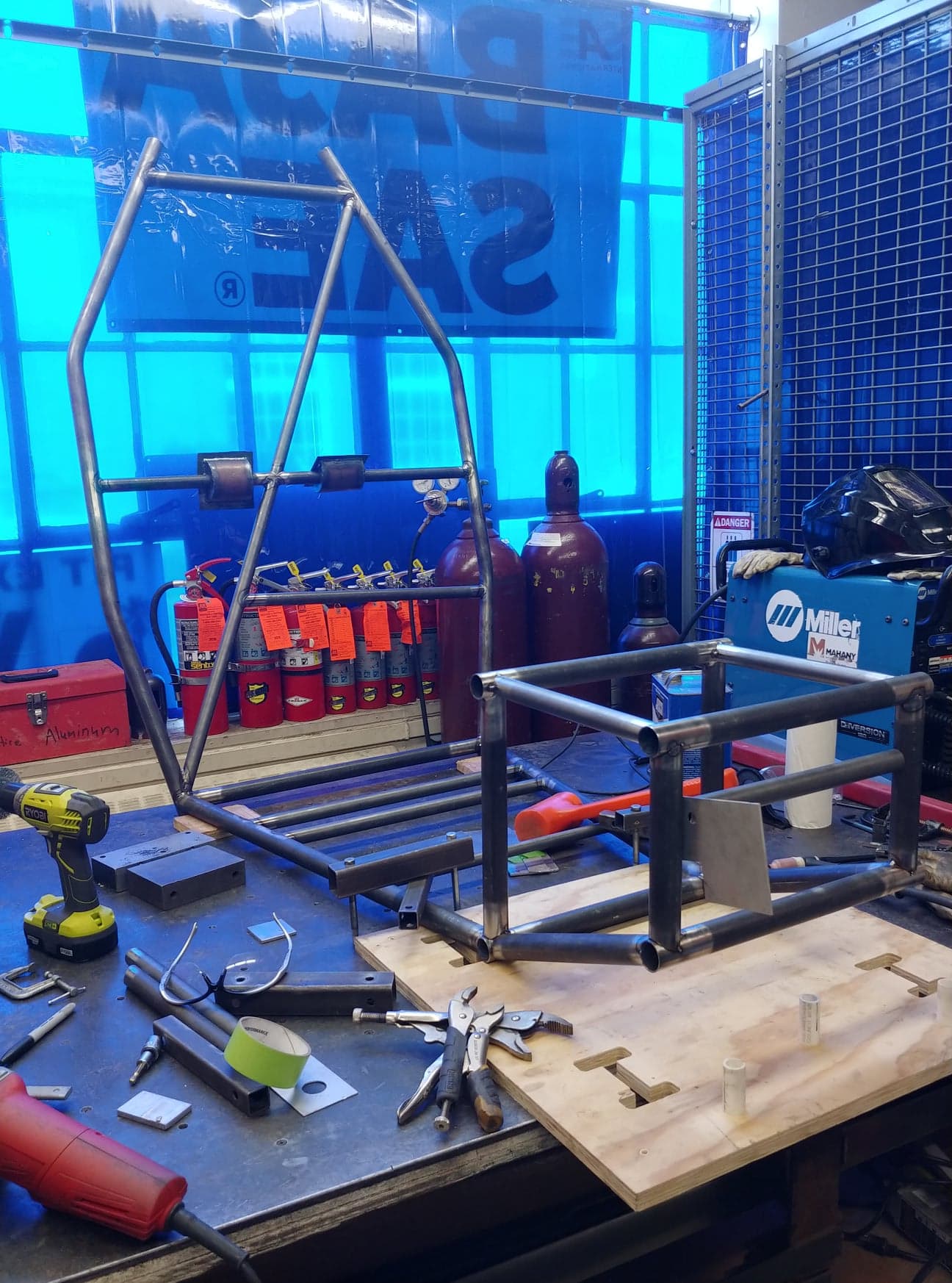
This image was taken at 7:30am. No, I hadn't gotten up early that day.
With the main parts together, the rest of the pieces went in with minimal issues. We ran some physical tests alongside our FEA in order to validate both our analysis and compare the CAD model with the frame we manufactured. With the tests being accurate from 1.1%-8%, it's official: this is the most accurate frame UR Baja has made yet!
...and I cant wait to see how they will make the next one even better!
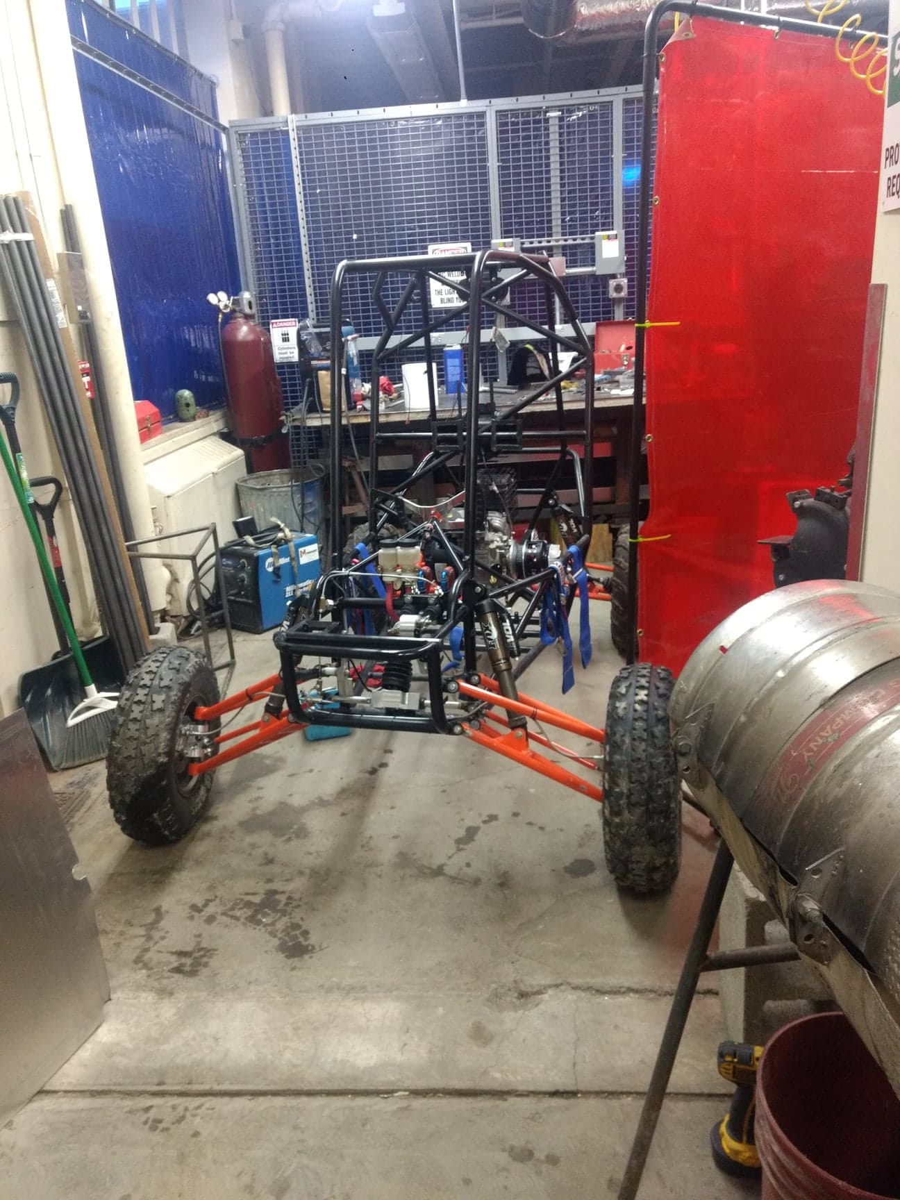
The skeleton of the frame completed!
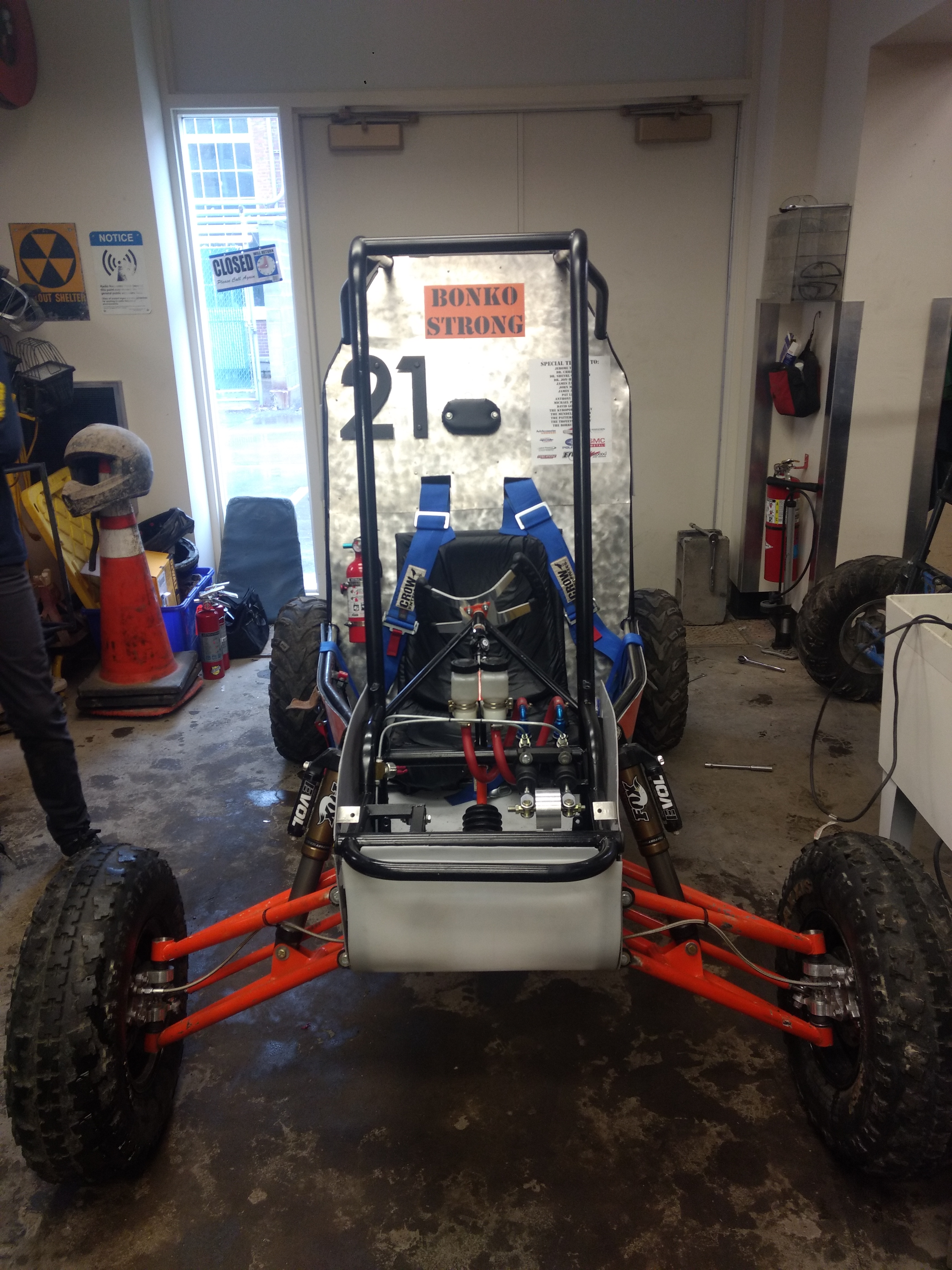
The finished car.
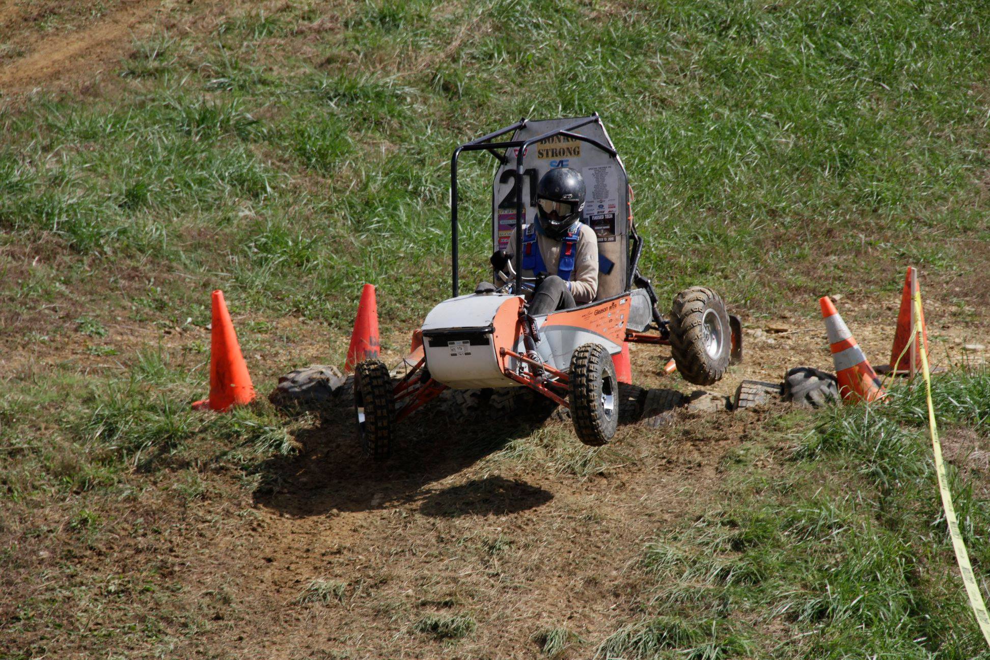
Was all that hard work worth it? Of course!
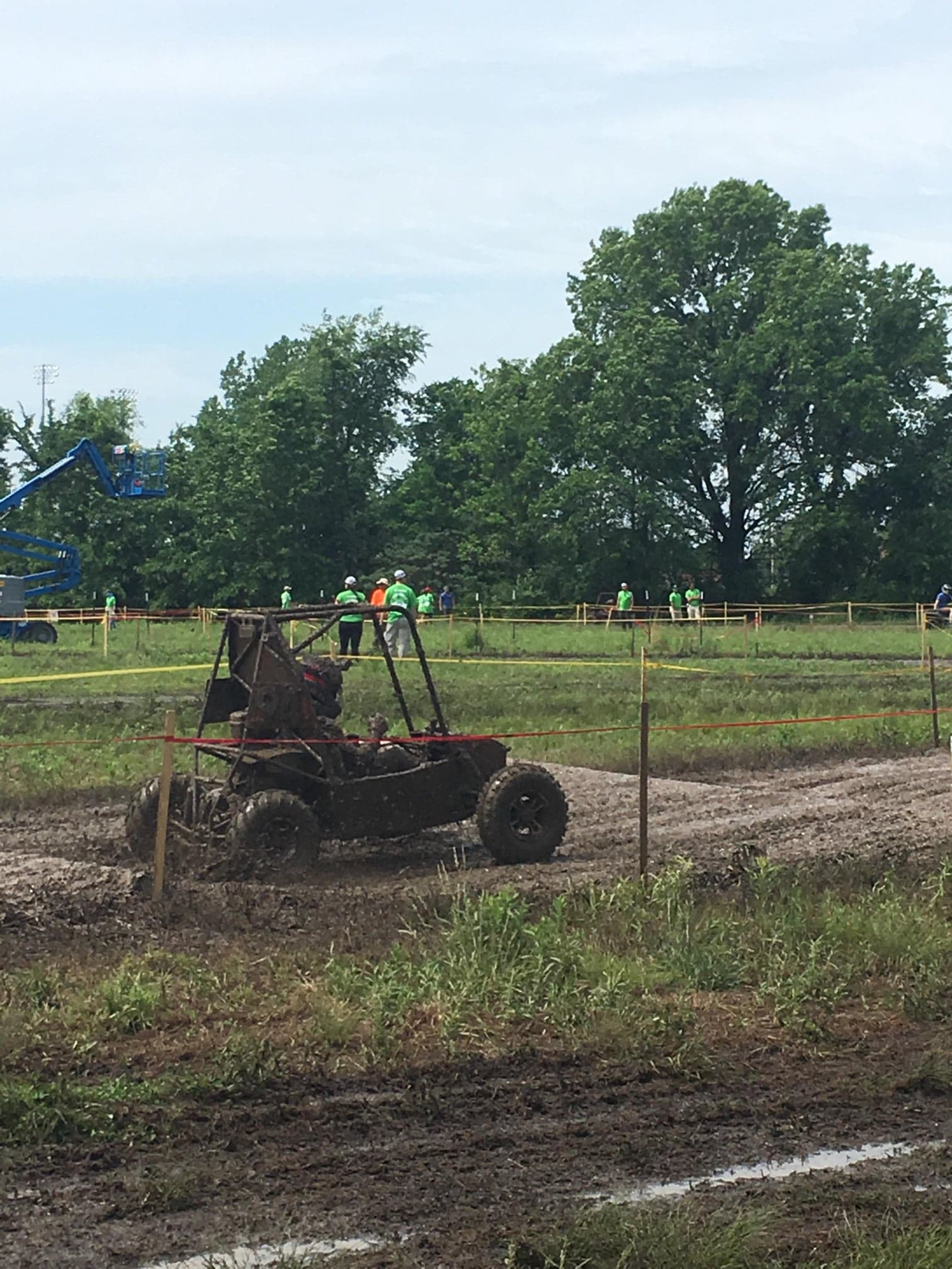
If you look closely, you'll see that there is a Baja car in this picture.
A special thanks to Dr. Christopher Muir for teaching me how to use the school's cnc router and always going above and beyond when helping our team.