Software and electronics: I have been wanting supplement my mechanical designs with electronic control for a while now, and this was a good project to start with. The plan was to use an Arduino Uno to communicate with a MPU 6050 gyroscope and accelerometer. After filtering the data from the MPU 6050, the robot can use it to calculate its position in space. This position should allow for PID control of the motors, resulting in a balancing robot. Sounds simple, right? If you want to skip to the code for this project, I posted it to GitHub: Balanging Robot Code

Assembled balancer, complete with a duct-taped on extra battery.
The first step in this project was to design the chassis. Since most of the components I used were quite common, I pulled the cad files from the internet. With everything already in CAD, it was really easy to design and print the frame. Unfortunately, my tiny battery pack couldn’t power both the Arduino and Motors, so I had to make some modifications with duct tape. Honestly, this probably made my job easier: a higher center of gravity makes it easier to balance an inverted pendulum. (Think of the difference between balancing a pen on your finger vs a yard stick.)

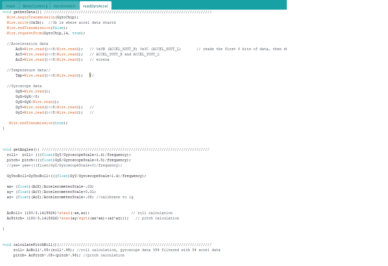
Code for communicating with the MPU 6050 chip.
After everything was assembled, wired and duct-taped, the real work began. My first challenge was reading the data off of the MPU 6050. There is a library for this specific chip, however, I wanted to do it on my own. The MPU 6050 communicated with Arduino using I2C, so I had to learn how to work with that. After I pulled the data off the chip, I needed to use some fancy trig to calculate the pitch and roll of the chip using the accelerometer data. This data would be combined with the gyroscope’s pitch and roll calculations. The gyroscope data is highly accurate in the short term but needs to be integrated so it tends to drift in the long term. The acceleration data is the inverse of the gyroscope data: stable in the long term but inaccurate in the short term. Combining them with the right filter negates the downsides of both, giving you accurate and stable angle readings.

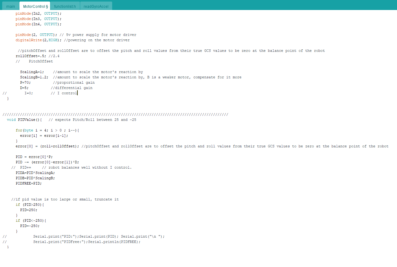
PID control for the robot. At least, it's PD control, there wasn't any need for "I" control.
With the pitch and roll sorted, this information can be incorporated into the motor control and tuned in order to balance the ‘bot. In my Systems and Vibrations course, I learned how to calculate the Butterworth (and other) values for optimal PID tuning. However, everyone online just derives them experimentally. Since it would be a real pain to calculate the exact center of mass for my duct-taped robot, I decided to jump on the bandwagon and go the experimental route.

Experimal PID tuning. In other words: crashing. Lots of crashing.
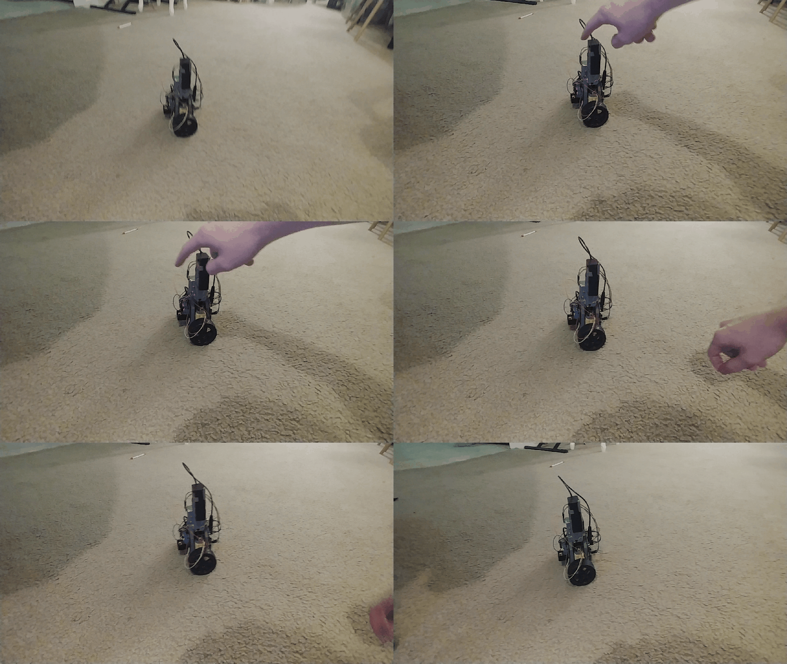
After some fine tuning and a close call involving my cat, the robot was able to stand on its own. It can even compensate for a small shove, but my motors are far too weak to deal with anything more strenuous.

It works!
Ironically, this project was supposed to apply my knowledge on PID tuning, but the thing I learned the most about was how to communicate with the MPU 6050 chip and how to process the data. Overall, I am very happy with this project and how much I learned while working on it. I look forward to tackling more and more challenging projects in the future.
A special thanks to An, who helped point me in the right direction when I got lost.