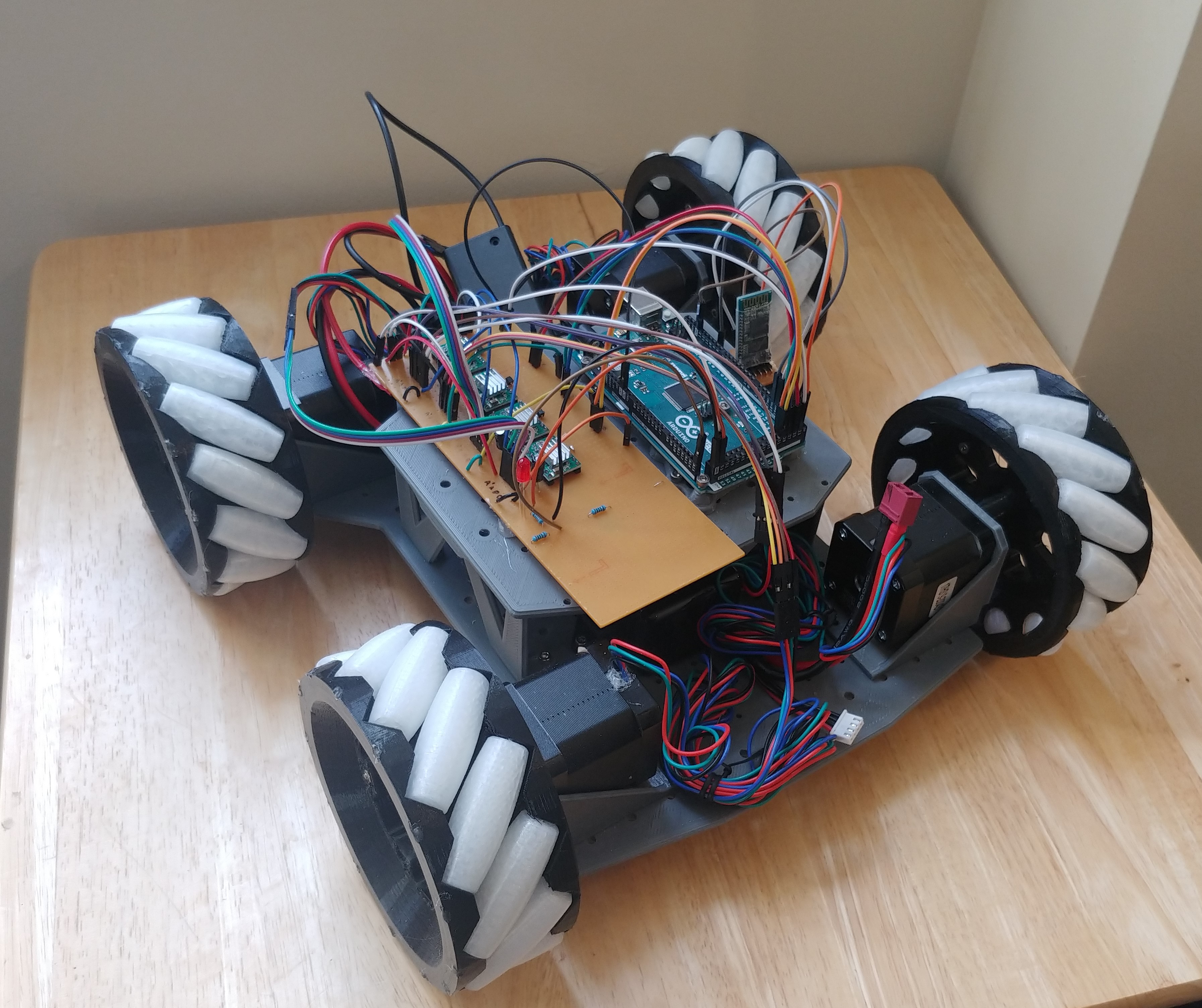
Sneak preview of the finished design.
Mecanum wheels are super interesting,
so I made a rc car around them. Eventually, I will attach some more sensors and maybe a more powerful controller and make it a real robot with “simultaneous localization and mapping” (SLAM) and some other basic functionality. However, for now, I wanted to focus on making the robot and maybe adding my own “spin” on the wheel design.
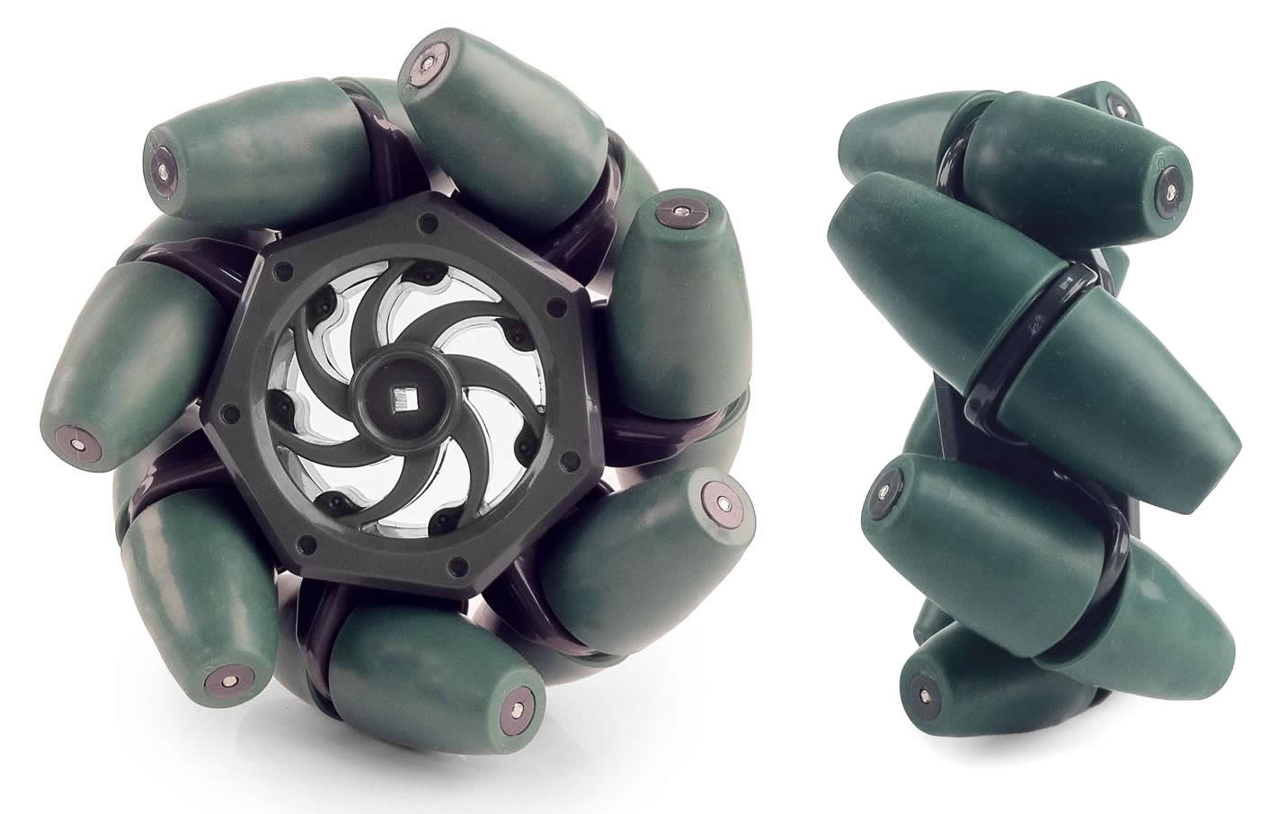
Commercially available mecanum wheels. Cool, but very expensive.
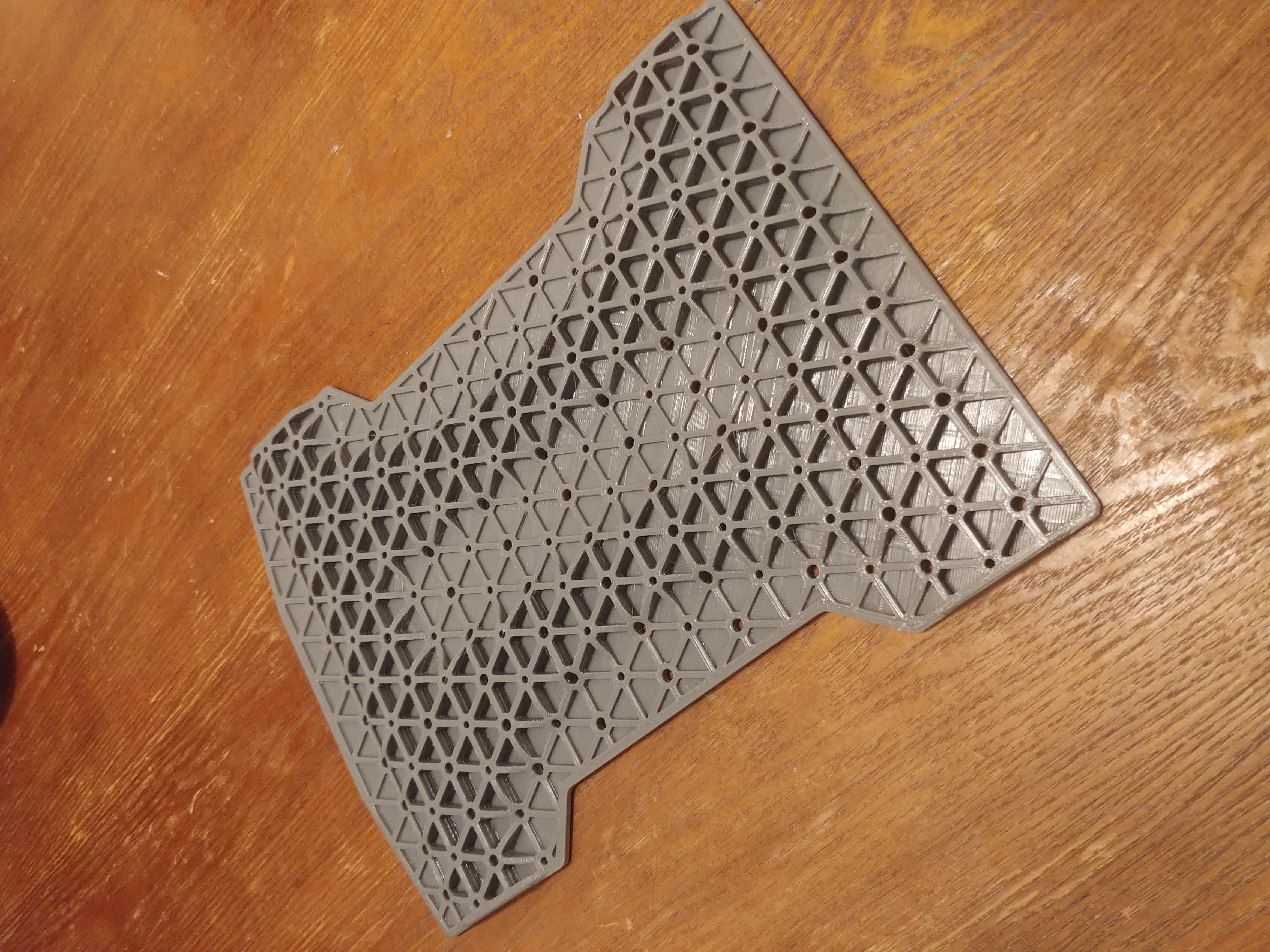
Chassis with isogrid reinforcement.
I made the chassis of the robot first. In order to meet my requirements, it needed to be quite stiff and modular. If the chassis is not properly stiff, it may cause discrepancies in how the wheels interact with each other, leading to many headaches on the software side. To achieve this, I incorporated an iso-grid on the underside of the body. Nasa has some interesting papers on this from the 80s but has since moved on to other methods. While it isn’t used on spaceships anymore, I thought it was perfect for my little project. My seccond requirement was modularity. This was so that I can make changes without having to reprint any large (35+ hour) parts. I achieved this by putting a grid of mounting holes in the chassis so that all manor of things can be mounted down the road.

Mecanum wheel mounted on a stepper. The white material is nylon. It makes a great bearing material because of its superior durability and low friction.
With the frame printing, I turned my attention to the wheels. After doing some research, I settled on a design and whipped it up in CAD. After printing a test model and making a few tweaks, I tossed them in my growing print queue. If I were to do this again (and I might), I would reduce the diameter of the wheels or add a gear reduction. As it stands, I have to drive the steppers slowly in order to have enough torque to maneuver on carpet.
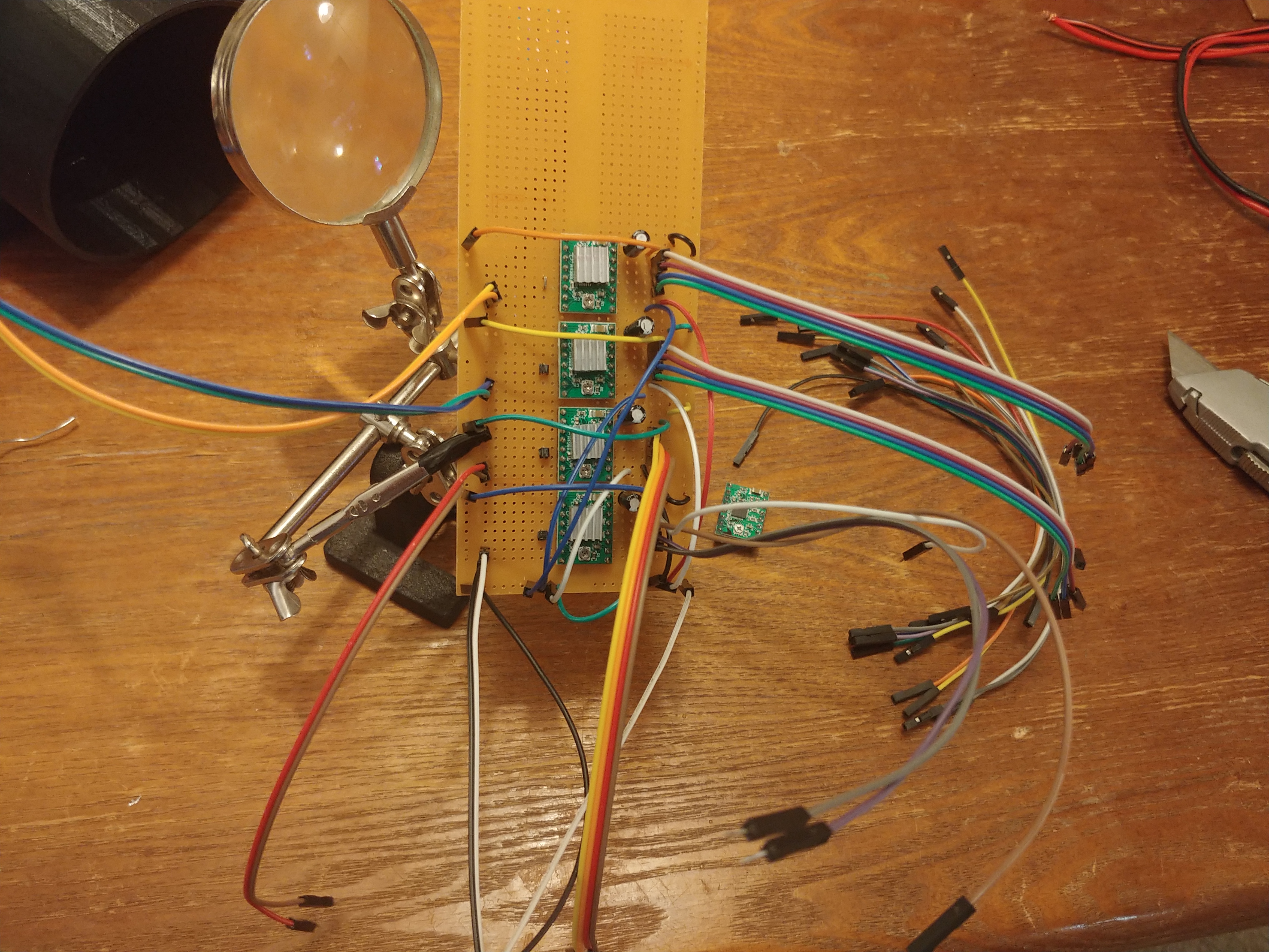
This was my first “real” soldering project and I am quite proud of it.
With the body of the frame sorted, I turned my attention to the electronics. The drivers I went with are chopper drivers, specifically meant for steppers. Originally, I used some generic dc drivers I already had, but they were inconsistent at best and rapidly overheated.
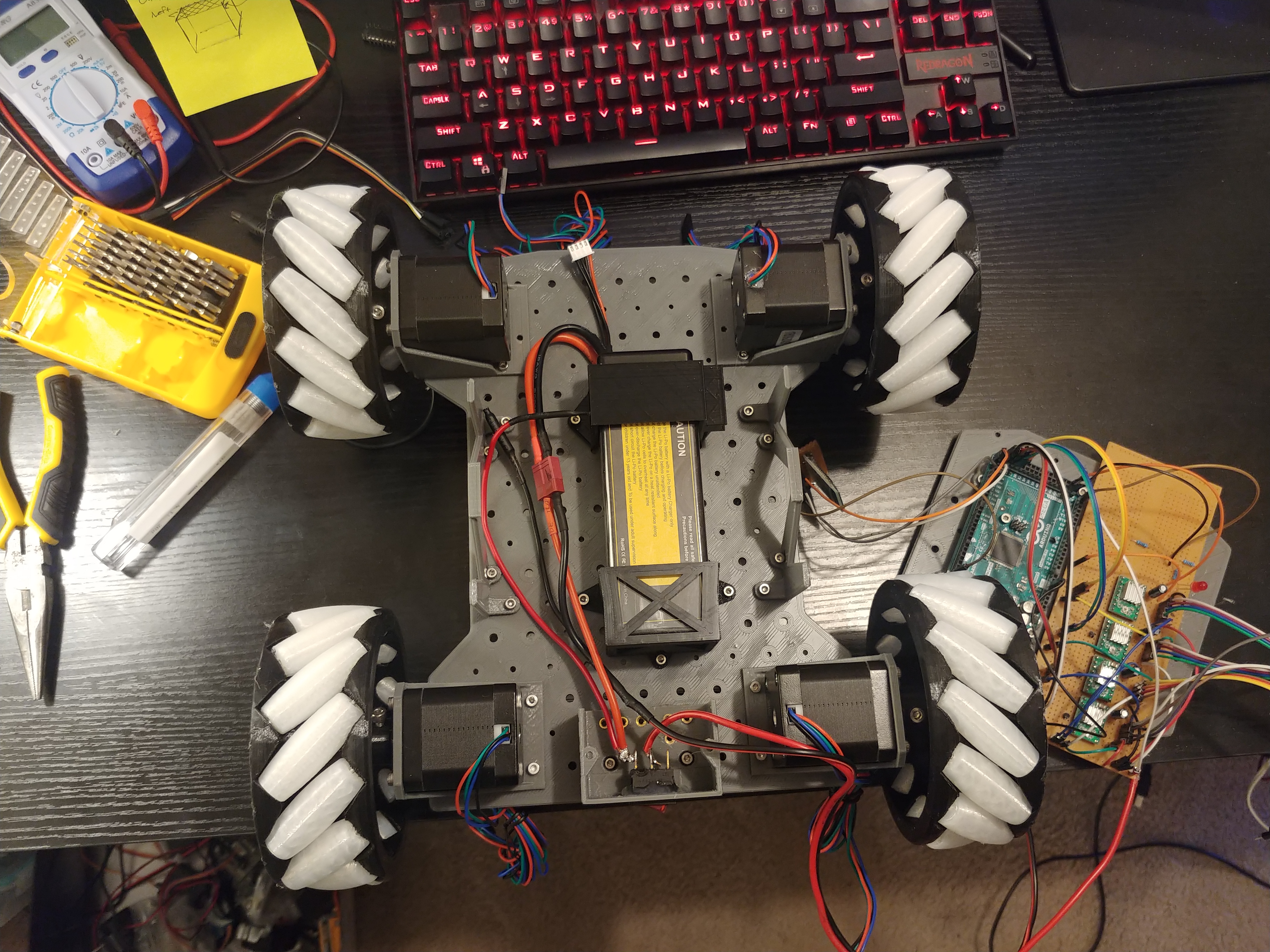
First layer: steppers and battery.
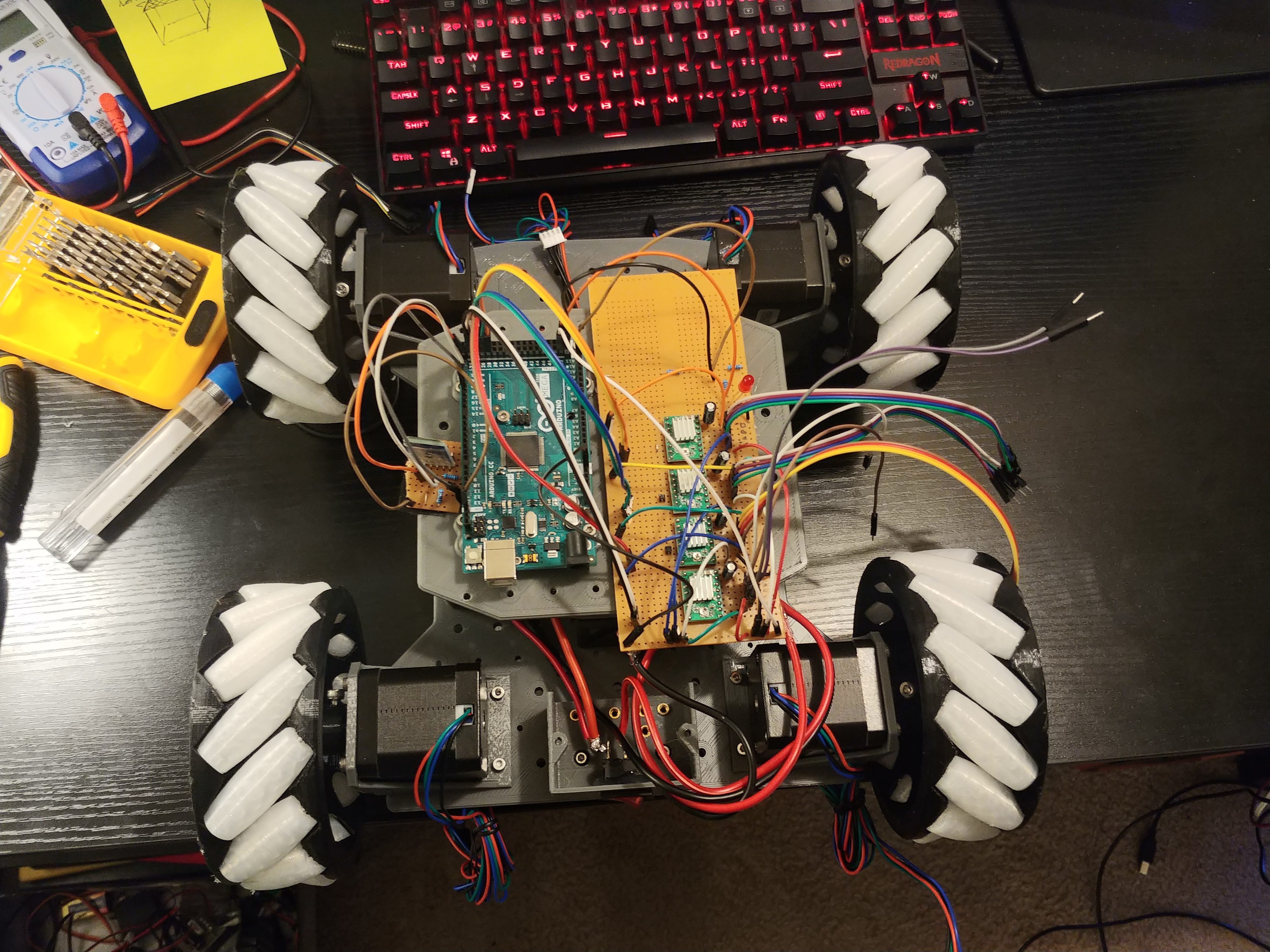
Seccond layer: Arduino, stepper drivers, and battery monitor.
After the components were assembled, I wrote the software to control it. A copy of my code is available on Github (link) but don’t look at it too closely. I was desperately trying to code this before school started again, and it is not well commented or formatted at all. With the motors running and everything communicating with each other properly, I attached a Bluetooth receiver to it and set it to take inputs from an app on my phone. With that finished, here is the final product:
Zipping around my kitchen. It has undergone a few software tweaks since then and drives much more smoothly, however my cats have decided that it is their new playmate, making it very hard to control, video, and fend them off.
I am looking forwards to adding some more “brains” to this ‘bot, but first I need to make a few revisions. It runs on carpet, but not as consistently as it does on tile floor, and I would like to iron that out first. Smaller tires or a simple gear reduction would be a good start. Also, mecanum wheels are quite inefficient- they lose a lot of energy to sliding friction when driving. I have an idea that would lock the rollers in place when the robot is doing simple maneuvers (forwards and backwards) and unlock for more complex control. Locking the wheels could theoretically improve efficiency by 30%, and I believe with proper pathfinding, they could be locked 80-90% of the time, resulting in massive energy savings.
A special thanks to An for helping me with some bugfixes and being a good resource throughout this whole project.