My end goal is to automate a rc car, but first I needed to make the car.
This way I could combine my love of mechanical engineering with the c++ I am trying to learn. In order to challenge myself on both fronts, I decided that I wanted to implement full suspension. It would force me to learn how to write a solid algorithm to deal with the uncertainty from dynamic suspension. In addition, it would give me some more practice working on very interconnected models. Anyways, designing suspension isn’t that hard, right? right? ...oh no

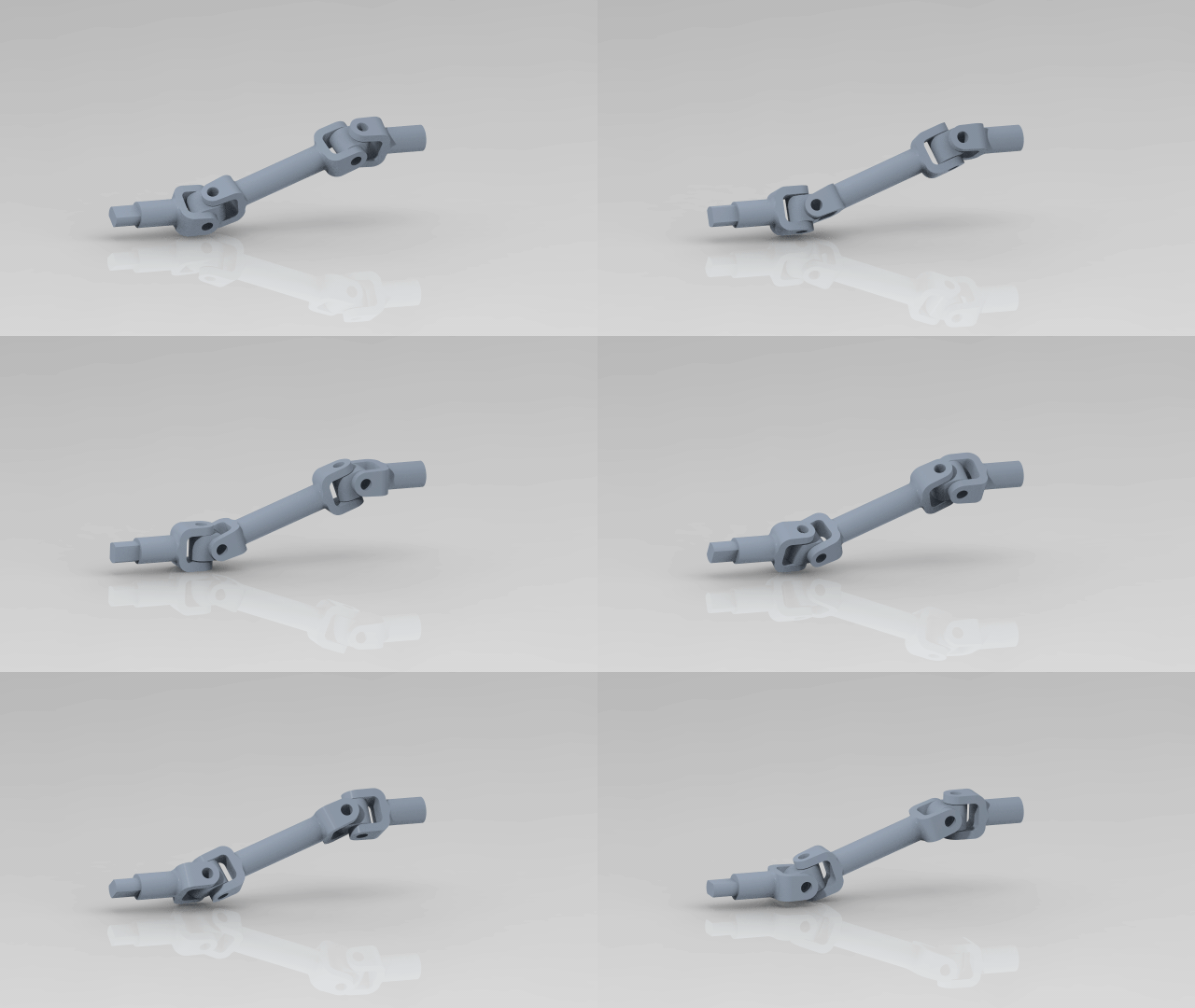
CV joint proof of concept.
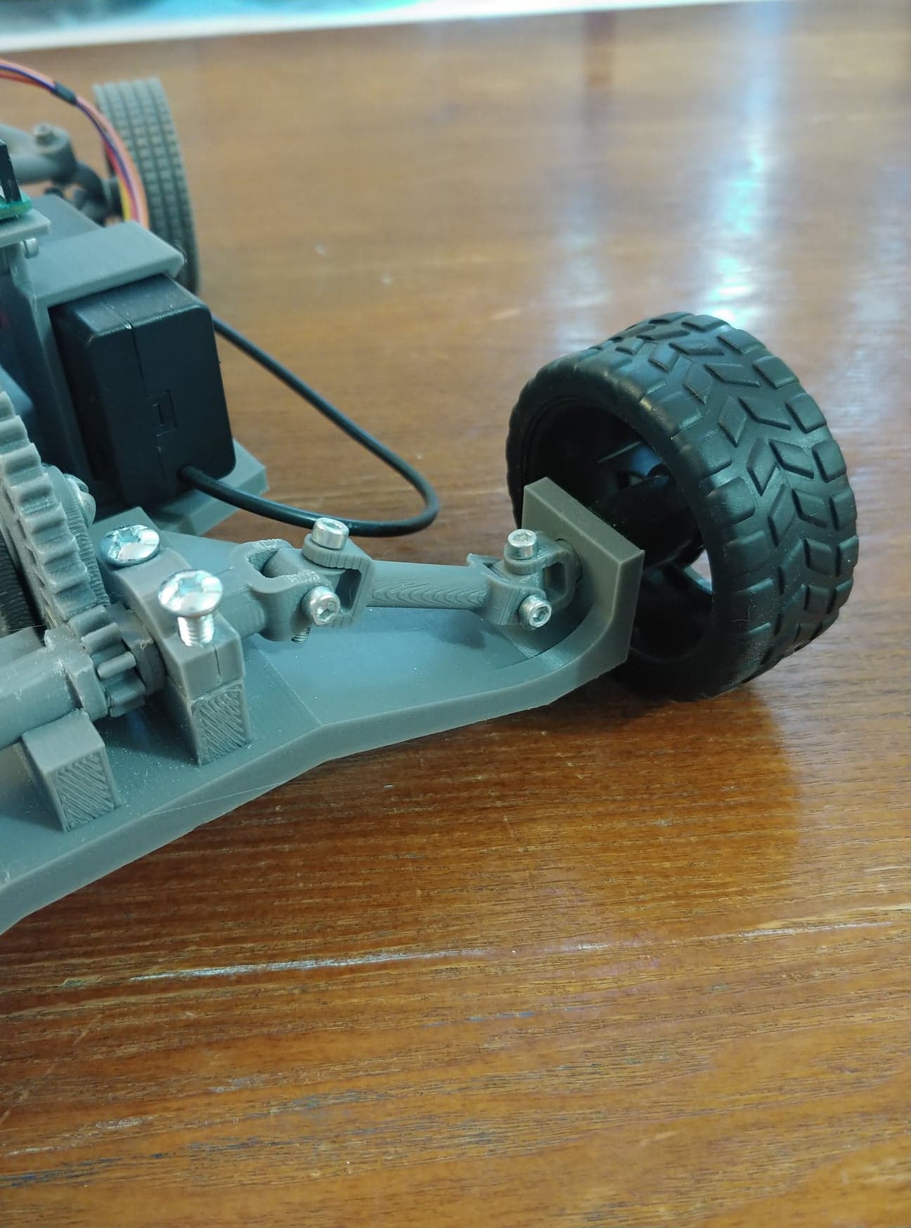
First, I designed a CV joint. I was unsure of my final geometry, but I did know that having a CV joint would give me a lot more freedom than a solid axle. After some reaserch, I settled on u-joints because they seemed to be the only resonable option for printing, and I wasn’t even sure about them. I shouldn’t have been so worried; they were a breeze to model and were much stronger that I had hoped when they were finished.
Upright (in white) assembled on the arms.
The first real hurdle I encountered was finding a joint for the uprights. In order to get a full range of motion, I would need a ball constraint. After looking at commercial RC cars, I concluded that most, if not all, use purchased I-joints for the connections. Since I wanted something cheaper and customizeable, I realized that I would need to design my own.
At the bottom of the ball joint, you can see the "bridge" I used to stabalize the ball for printing.
After some trial and error, I figured out how to print decent ball joints in-place and in any orentation I desired. The only caviat is that I needed to add a small bridge connecting the ball to the piece below. This gave the ball a small starting point for my printer to work off of and resulted in joints with more precise clearences and less slop. After printing, I could break the bridge by rolling the ball in its socket untill it smoothed out.
Completed front suspension.
Next came the fun part: the suspension itself. I went with 100% Ackermann geometry because I want to minimize slipping when this thing turns. I was starting to feel like there were already enough unknowns for me to program for! I also decided on a slightly positive camber and no kingpin inclination to keep things simple for steering.
Compliant cantilever beam that functions as a decent shock absorber.
I didn’t have any springs lying around, so I modeled up a compliant 3D printed beam as a placeholder. The idea was to have it hold the suspension at a fixed position so that I could make a prototype and test it without dealing with much suspension travel. After printing it, I relized that it worked much better than I expected and gave resistance through the suspension’s full range of motion. Additionally, it packaged very neatly in the suspension so I kept it in the current design. I still may swap them out later, but I am more than happy with it for now.

The rear suspension.
At the desgin stage I am in right now, the rear suspension is still rigid. I designed it quickly in order to get a working prototype out before school started again, and intend on swapping out the components as soon as I get a good chunk of time.

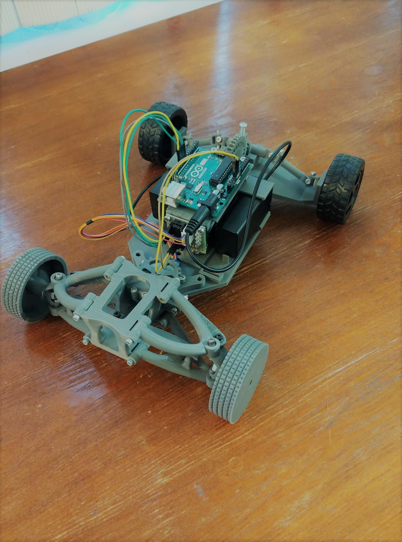
The completed first prototype!
A special thanks to www.buildyourownracecar.com for being such a great resourse on suspension design.